
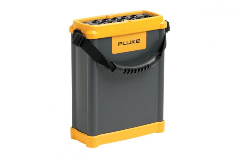
Fluke 1750/B
Three-Phase Basic Power Quality Recorder
Power quality that meets the standard All measurements comply with IEC61000-4-30 standards for correct evaluation of all measured values including voltage, current, power, harmonics, flicker etc. Quick and reliable configuration A tablet computer provides a window into what the instrument is recording, enabling quick and reliable configuration even in awkward test locations
-
모델명
Fluke 1750/B
- 금액 견적문의
상세정보
Record every power quality parameter, every cycle, all the time
Setting up a power quality analyzer to capture detailed power quality data has never been easier that it is with the Fluke 1750. The only things you need to know are the system voltage, frequency and the power configuration (delta or wye). The analyzer then captures the most important data for up to 30 days without losing the most important details. These power meters automatically record every power quality parameter and event, on every cycle – all the time. Once the data is captured download via Ethernet or directly to 2GB SD card (without the need of any other device). The Fluke 1750 features a wireless front panel for viewing measurements, data and setting up, implemented via a tablet computer using Bluetooth communication.
Applications
- Long-term analysis: Uncover hard-to-find or intermittent issues; monitor critical equipment, capturing power quality events to correlate with equipment malfunction
- Power quality surveys: Quantify power quality throughout a facility, documenting results with professional reports
- Quality of service compliance: Validate incoming power quality at the service entrance
- Equipment Installation/Commissioning: Benchmark: power system prior to install to insure quality of service
- Long-Term Analysis – Uncover hard-to-find or intermittent issues.
- Load Studies – Verify the available electrical system capacity before adding loads.
| Technical Specifications | ||
| Power quality measurement standards | Conformance | IEC 61999-1-4 Class 1, IEC 61000-4-30 Class A or B depending on measurement function, IEEE519, IEEE1159, IEEE1459 and EN50160 |
| Clock/calendar | Leap years, 24-hour clock | |
| Real-time clock accuracy | Not more than ±1 s/day | |
| Internal memory capacity for data | At least 2 GB | |
| Maximum recording period | At least 31 days | |
| Measurement time control | Automatic | |
| Maximum number of events | Limited only by the size of the internal memory | |
| Power requirements | 100 to 240 Vrms ±10%, 47-63 Hz, 40 W | |
| Operating time during interruptions (internal UPS operation) | 5 minutes per interruption, 60 minutes total operating time without recharging | |
| Dimensions | 215 x 310 x 35 mm (8.5 x 12.2 x 3.5 in) | |
| Mass (weight) | 6.3 kg (14 lb) | |
| Input | Measurement types | One Phase Plus Neutral, One Phase IT No Neutral, One Phase Split Phase, Three Phase Wye, Three Phase Delta, Three Phase IT, Three Phase High Leg, Three Phase Open Leg, 2 Element Delta, 21/2 Element Wye |
| Input channels | Voltage: 4 channels, AC/DC | |
| Current: 5 channels | ||
| Voltage channels | Input resistance: 2 MΩ | |
| Input capacitance: < 20 pF | ||
| Current input characteristics | 2 Vrms = full scale, 1 MΩ Input Impedance for ferro CTs, low impedance for Flexi-CTs | |
| Measuring method | Simultaneous digital sampling of voltage and current. Digital PLL synchronized sampling, internal frequency reference used during voltage drops. | |
| Synchronization and sampling | PLL-synchronization source | The PLL synchronizes to the A-N voltage for wye power types, and to the A-B voltage for delta power types. All listed power types can be characterized as either wye or delta. |
| PLL lock range | 42.5 to 69 Hz | |
| Sampling frequency | Voltage and current: 256 samples/cycle Inter-harmonics per IEC 61000-4-7: 2 560 points/10 cycles (50 Hz), 3072 points/12 cycles (60 Hz) Transient Voltage: 5 MHz | |
| A/D resolution | Voltage and current: 24 bits | |
| Transient voltage: 14 bits | ||
| Voltage and current measurements | Voltage measurement range | AC voltage: 1000 Vrms ±10% over range |
| DC voltage: ±1000 V +10% over range | ||
| Voltage crest factor | 3 or less | |
| Current measurement range | Depends on current probe used | |
| Current crest factor | 4 or less | |
| RMS voltage | Measurement type | True RMS calculated continuously: every cycle, every 1/2 cycle, and every 10 or 12 cycles at 50 or 60 Hz respectively, as required by IEC 61000-4-30. |
| Measurement uncertainty | AC: ±0.2% reading ±0.1% full scale, above 50 Vrms | |
| DC: ±0.5% reading ±0.2% full scale, above 50 VDC | ||
| RMS current | Measurement type | True RMS calculated continuously: every cycle, every 1/2 cycle, and every 10 or 12 cycles at 50 or 60 Hz respectively, as required by standards |
| Transient voltage (impulse) | Measurement type | Waveshape sampling |
| Full scale | 8000 V pk | |
| Sample resolution | 200 nS | |
| Measurement uncertainty | ±5% reading ±20 V (test parameters: 1000 VDC, 1000 Vrms, 100 kHz) | |
| Voltage swell (rms swell) | Measurement type | True RMS (one cycle calculation by overlapping each half cycle - voltage between lines is measured for 3P3W lines and phase voltage is measured for 3P4W lines) |
| Displayed data | Amplitude and duration of swell | |
| Measurement | Same as rms voltage | |
| Voltage dip (rms sag) | Measurement type | True RMS (one cycle calculation by overlapping each half cycle - voltage between lines is measured for 3P3W lines and phase voltage is measured for 3P4W lines) |
| Displayed data | Amplitude and duration of dip or interruption | |
| Measurement | Same as rms voltage | |
| Voltage dropout (interruption) | Measurement type | Same as voltage dip |
| LAN interface | Connector | RJ-45 |
| Speed and type | 10/100 Base-T, auto MDIX | |
| Communications protocol | TCP/IP over Ethernet | |
| Wireless controller interface | Connection | wireless (2.4 GHz radio) |
| Speed | up to 700 kbit/second | |
| Communications protocol | Bluetooth SPP | |
| Power Measurements | ||
| Power, battery life | Measurement type | True RMS calculated continuously: every cycle, and every 10 or 12 cycles at 50 or 60 Hz respectively, as required by standards |
| Frequency | Measurement range | 42.5 to 69 Hz |
| Measurement source | Same as PLL synchronization source | |
| Measurement accuracy | ±10 mHz (10 to 110% of range, with sine wave) | |
| Power factor | Measurement range | 0.000 to 1.000 |
| Measurement accuracy | ±1 digit from the calculation of each measured value (±3 digits for total) | |
| Displacement power factor | Measurement method | Calculated from the phase difference between voltage fundamental and current fundamental |
| Measurement range | - 1.000 (leading) to + 1.000 (lagging) | |
| Measurement accuracy | ±0.5% reading ±2% full scale ±1 digit | |
| Voltage unbalance and phase sequence | Measurement method | Positive sequence voltage divided by negative sequence voltage, per IEC 61000-4-30 |
| Harmonic voltage and current | Analysis window | rectangular |
| Analysis order | 1st to 50th order | |
| Measurement accuracy | Voltage / Current: 1st to 20th orders: ±0.5% reading ±0.2% full scale, 21st to 50th orders: ±1% reading ±0.3% full scale (current sensor accuracy must be included for current and power) | |
| Measurement method | IEC 61000-4-7 | |
| Inter-harmonic voltage and current (intermediate harmonics) | Analysis window | rectangular |
| Analysis orders | 1.5 to 49.5th order | |
| Measurement method | IEC 61000-4-7 | |
| Flicker | Measurement method | IEC 61000-4-15 |
| Plt for 2 hours and PSt for 10 minutes | ||
| Measuring range | 0,1 to 5 (25) depending on voltage level, modulation and frequency | |
| Environmental Specifications | ||
| Environmental | Operating environment | Indoors or in covered area outdoors, up to 2 000 m altitude |
| Storage temperature and humidity | -20°C to 50°C, 80% RH max, non-condensing | |
| Operating temperature and humidity | 0°C to 40°C, 80% RH max, non-condensing | |
| Maximum rated working voltage | Voltage terminals | 1100 Vrms |
| Voltage durability | 5550 Vrms AC for 1 minute, between voltage input terminals, voltage input terminals and current probes, and voltage input terminals and case (50/60 Hz, 1 mA sense current) | |
| Enclosure protection | IP30 (per EN 60529) | |
| Standards | EMC | EN 61326-1:1997+A1:1998 Class A |
| EN 61000-3-2:1995+A1:1998+A2:1998 | ||
| EN 61000-3-3:1995 | ||
| Safety | EN 61010-1 2 nd Edition; 2 000 | |
| Voltage input unit: Contamination Level 2 , Overvoltage Category 1000 V CAT III, 600 V CAT IV (anticipated overvoltage: 8000 V) | ||